Engine Head Investigation
For a number of reasons I thought it necessary to remove the head of the engine on TC4985. These reasons include:
- I have no idea whether or not the head has been modified for unleaded petrol.
- I don't know what, if any, work was done on the engine when the car was returned from the US.
- It looks as though oil is getting into the fourth cylinder, hopefully just due to a defective valve stem oil seal.
- The engine is running rich, with constant build-up of soot on the plugs. I've tried making the mixture leaner, but that hasn't helped much.
- The fuel consumption is very poor at around 24 mpg, whereas is should be more like 35 mpg.
- The engine seems to lack power, having trouble getting up hills. Compression tests also indicate low pressure in all cylinders.
So after a successful 2018 South Downs Run (136 miles over the day) I decided that the time was right to tackle the job. It would also give me a chance to examine the wear in the bores, with the option of extending the work to replace piston rings.
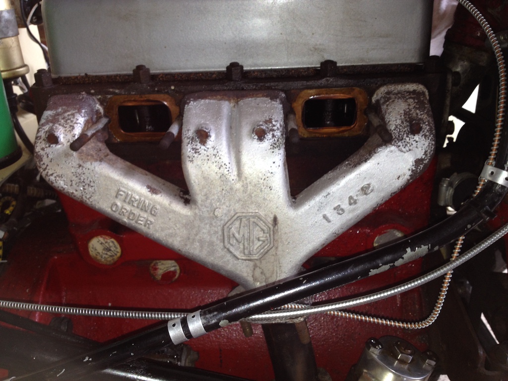
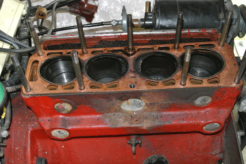
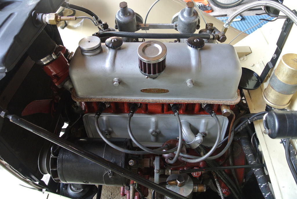
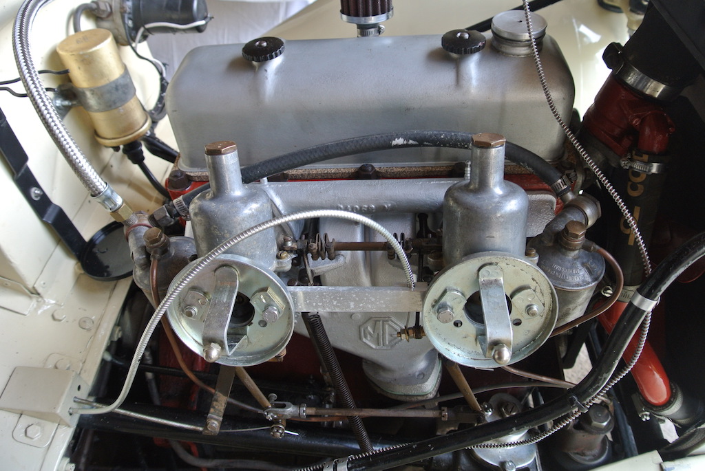
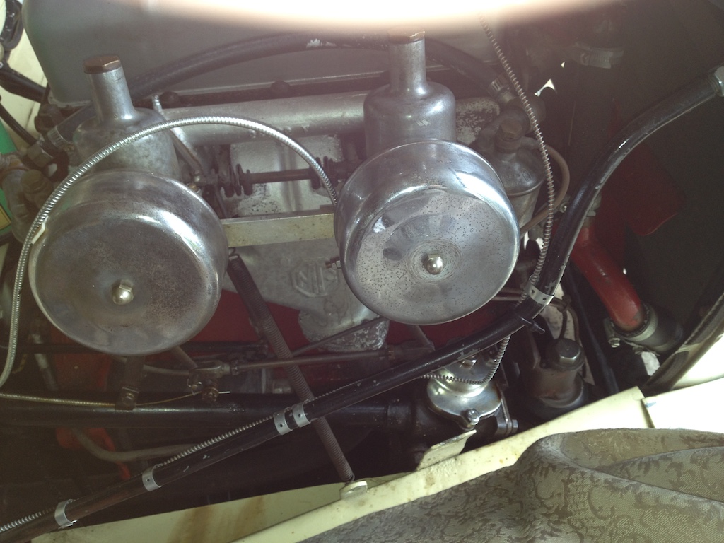 So on Tuesday 4th September I removed the bonnet I disconnected the linkages and fuel line from the carburetters and removed them. The first photo shows the engine before I started and the next shows it after removal of the carburetters. In fact I took several photos as a reminder of how the bits go together. Getting the nuts off the exhaust flange was another matter. One came off, but the other two are hardly accessible and tight! So I squirted them with GT40 and left them until the morning. So the next day I removed the remaining two nuts holding the exhaust to the manifold. To reach the back nut I had to remove the off-side wheel and approach the nut from below. I then removed the inlet and exhaust manifolds and drained the coolant.
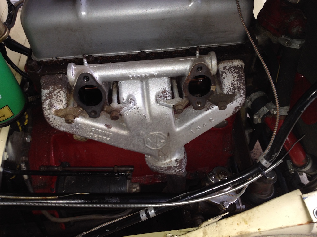
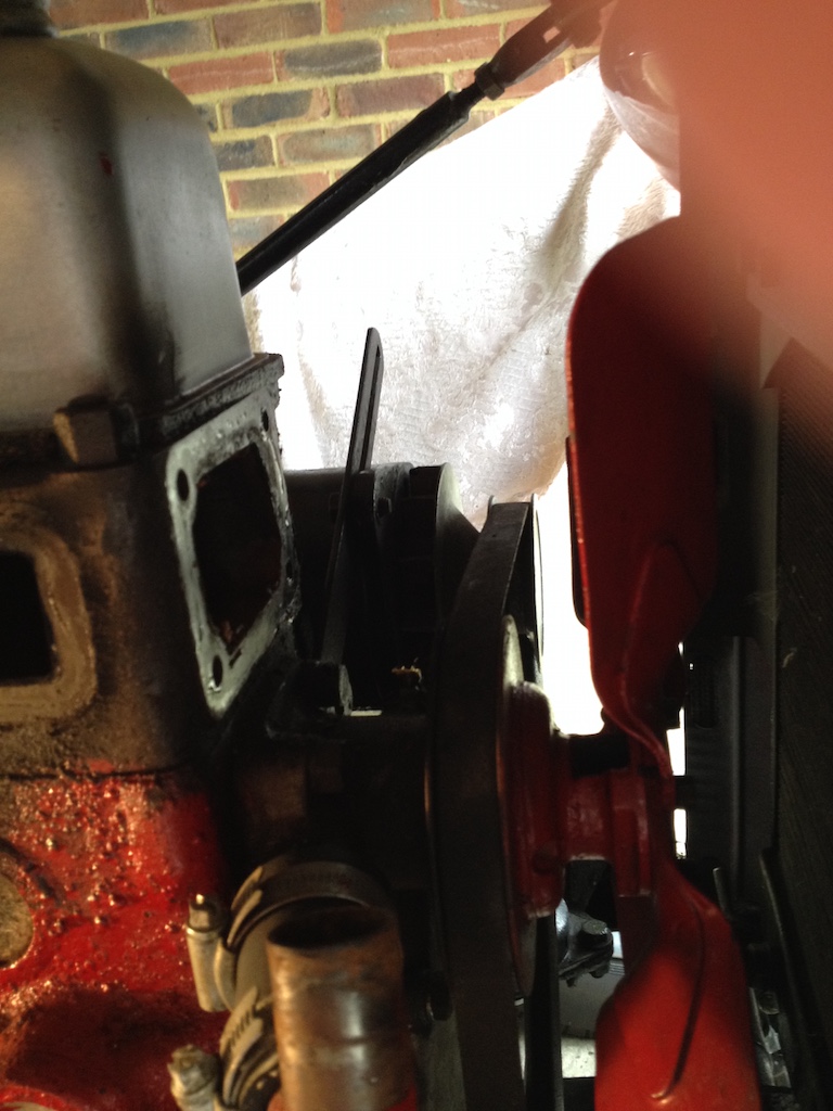 The next stage was to separate the engine from the cooling system. Since the top hose is impossible to remove on its own, this is achieved by removing the bypass hose and then the thermostat housing. Interestingly, there was no thermostat! However, the engine seems to warm up quickly and not overheat.
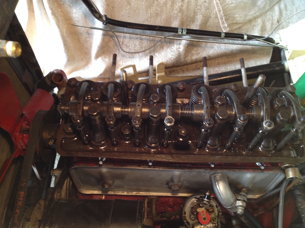
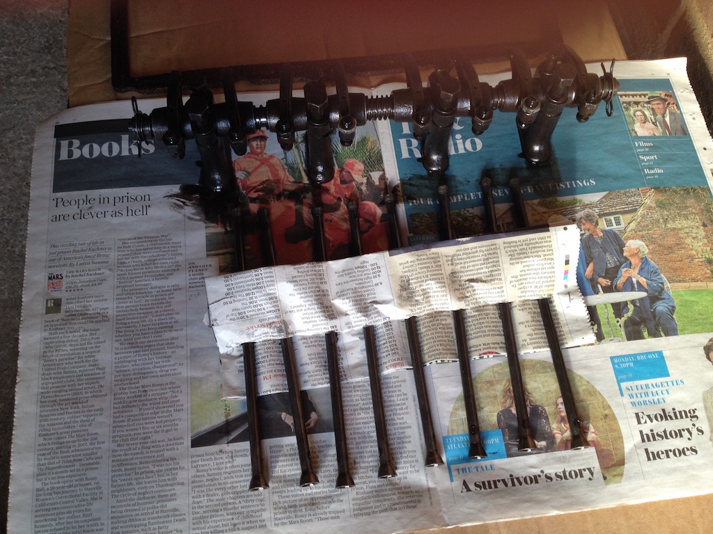
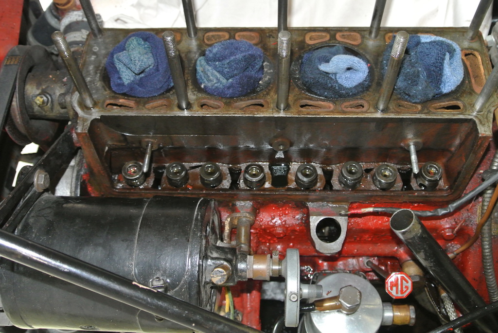
The next photo shows the engine from the near side. At this point I've removed the banjo bolt from the oil feed pipe to the rocker gear and loosened the side plate enough to free it from the head. Following that we see the rocker gear removed from the head and the push rods extracted. The latter were put into marked slots in a sheet of newspaper so as to ensure they go back in the same order.
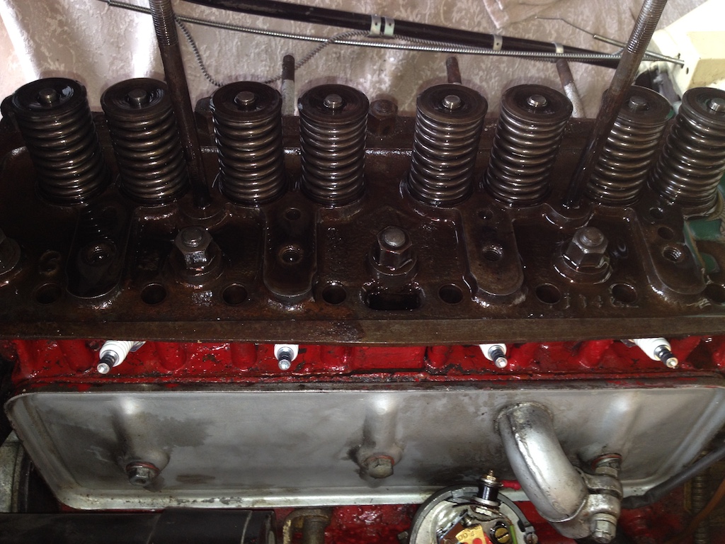
 I had left the spark plugs in place since I thought it might be difficult to remove the head and that I might need to turn the engine over and allow the compression to lift the head off the block. However, a little hand jiggling of the head freed it from the block and I was able to lift it off and put it on the bench.
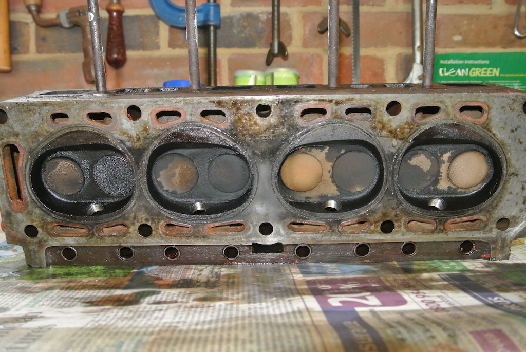
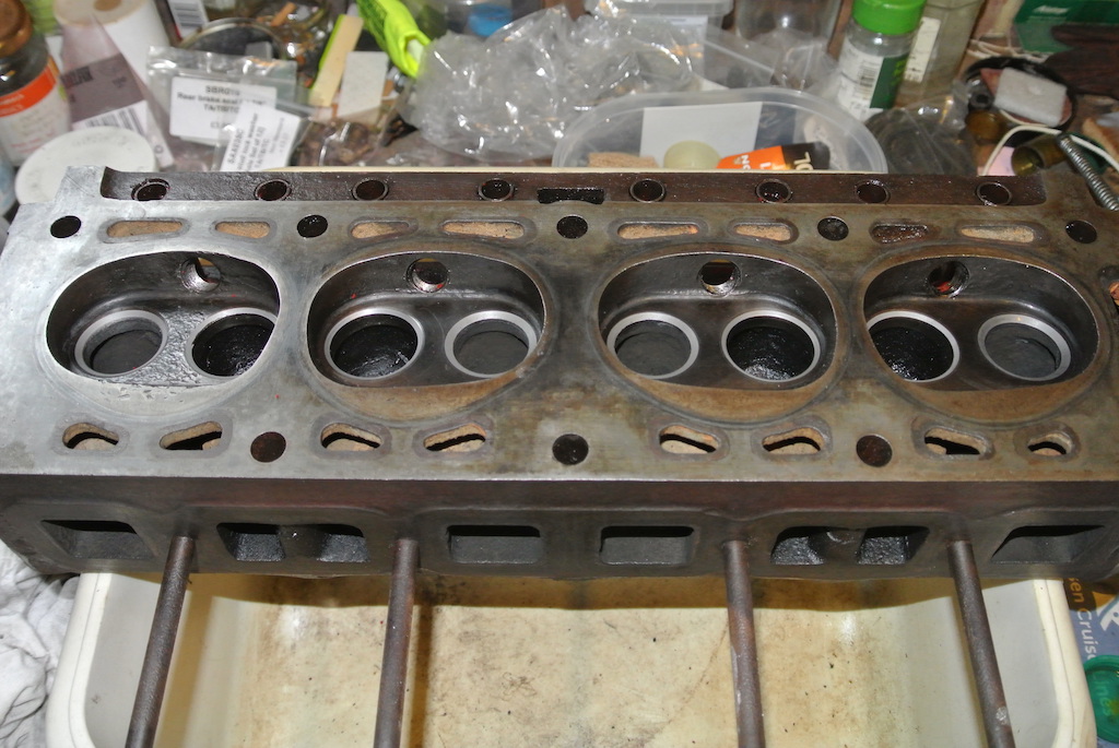
The photo on the right shows the state of the valves and inside of the combustion chambers. Clearly, oil is entering the fourth cylinder via the inlet valve.
Head Dismantling and Cleaning
Luckily I still have the valve spring compressor that I bought in the 1980s when I took the head off the spare engine for our Morris 1000 Traveller. So I was soon able to remove the valves from the head. The diagram (taken from Sherrell, page 133) shows the components and, in particular, the position of the valve stem oil seal (item A).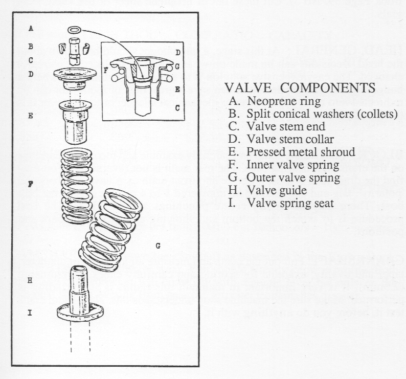
I found that, for some reason, the oil seal on the inlet valve of cylinder four was of a completely different type to the others and it had broken! This explains the oil in cylinder four, much to my relief.
This is one of the valves and you can see the carbon deposits. The photo of the combustion chambers in the head is after I'd removed any deposits and the valves had been ground in. As with the valve spring compressor, I still had the valve grinding tool and the two pots of carborundum paste (one coarse and one fine) from the Morris 1000 work. The valves themselves needed deposits scraped off, but the grinding process was quite quick since the two surfaces were not pitted.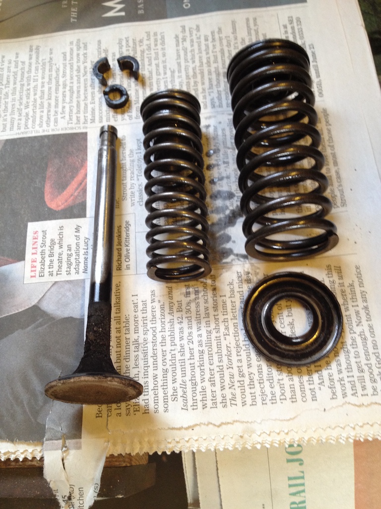
 It was clear that hardened valve seats have not been installed, so I will need to continue putting lead substitute additive in the petrol. I also discovered that the valves, all of which seemed in reasonable condition, were the standard size; inlet 33 mm and exhaust 31 mm.
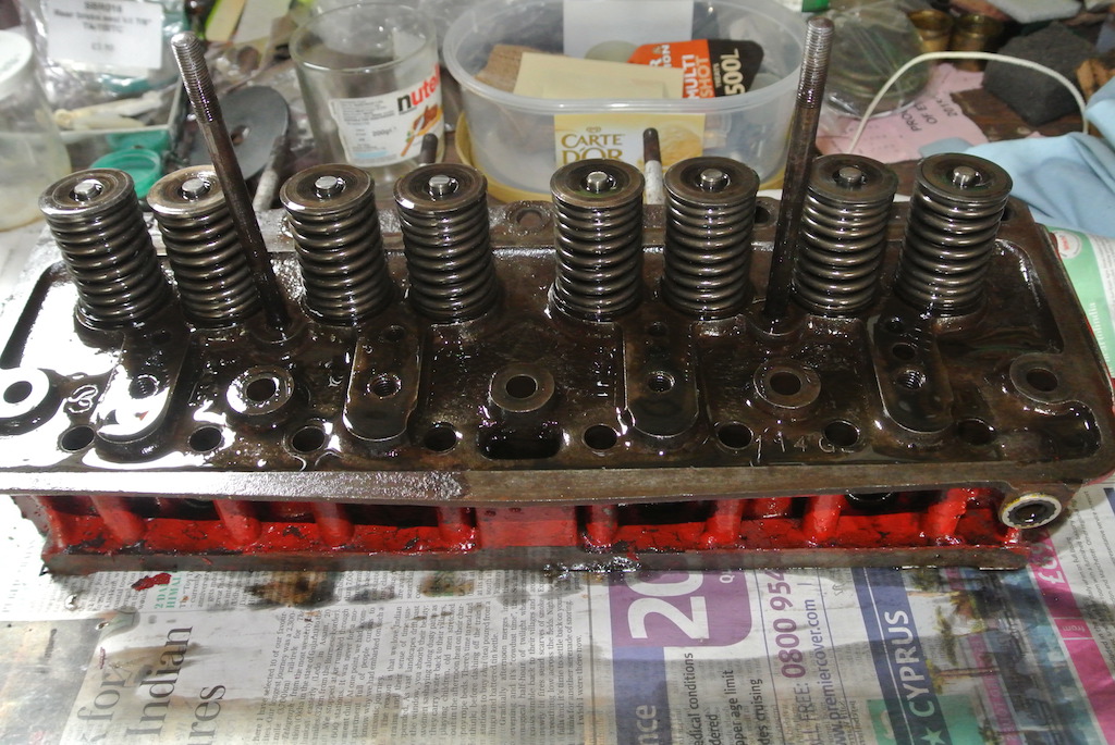
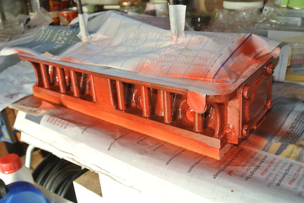
The red paint on the head was flaking off. I couldn't find any brush-on paint of the right colour, so I bought a spray can of high-temperature paint, squirting some into a plastic lid so as to use a brush where necessary. I scraped off the old paint and cleaned the head with de-greaser and then thinners. The photo shows the head masked for spraying and one coat applied. The paint was more like a lacquer and almost translucent, so I gave the various parts two coats and 'touched up' some areas. I had been concerned that the colour was lighter than the original, but because the underlying metal seems to show through, the colour matches fairly well.
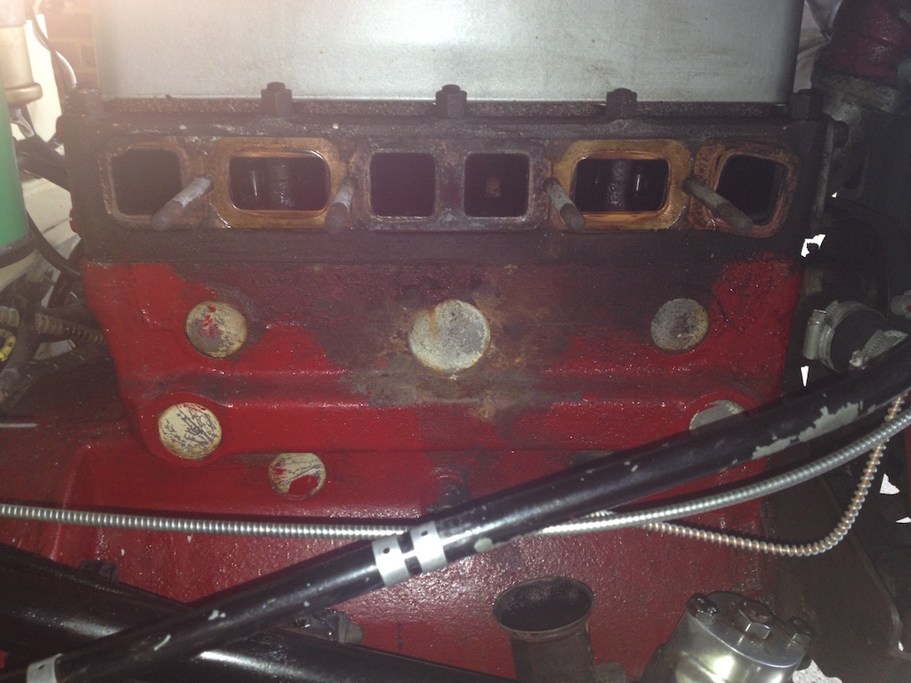
You can see in the photo of the block (above) that the block had not been painted under the manifolds. So I cleaned the top part of the block in the same way and gave it a couple of coats of paint. I also repainted the water pipes to the radiator and used a high temperature aluminium spray paint on the inlet and exhaust manifolds.
Inspection and Re-assembly
With the head off, not only was I able to clean the top of the block and the top of the pistons, but I was also able to inspect the cam followers and measure the cylinder bore. So I scraped the top of the block, using a plastic scraper on the top of the cylinders, raising each piston to the top in turn. I was careful not to disturb the ring of carbon at the top of the cylinder bores. I then cleaned the top of the pistons and the top of the block with petrol.
 Six of the cam followers looked fine, no crazing or noticeable wear. However, the other two had a little crazing.
I measured the cylinder bores as 66.93 mm, whereas the standard bore is 66.5 mm. Bearing in mind that there was a slight carbon ring around the top of each cylinder, this is nearly equal to the first oversize of 0.5 mm (see Smith, 1956, chapter 19).
Having cleaned everything I dropped the gasket and then the head on to the block and put on the nuts finger tight. Following the order in the 'brown book' I torqued the nuts gradually (20 lb.ft, 30, 35, 40, 45 and finally 50 lb.ft). I'd read that the studs could be taken beyond their elastic limit and stretch so that they never reach 50 lb.ft. But I had no problem getting there. I then refitted the side plate (with a new cork gasket) and the rocker gear and set the valve clearance cold, just to get an initial setting.
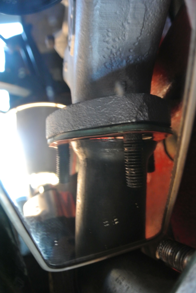 I had wondered why there were two manifold gaskets in the 'head gasket' set. I turned out that one was slightly longer than the other, so only one would fit over the studs. The manifolds went back on after a little easy around the studs, but connecting the exhaust pipe to the manifold was a more difficult. As you can see from the photo (taken in a mirror) they did not line up. Luckily, with the new gasket, tightening the nuts pulled the two together.
After refitting the carburetters (see below) and the distributor I statically adjusted the timing. Much to my delight, the engine start immediately on pulling the starter knob. As suggested by Wood (1968, page II-11) I ran the engine for a few minutes, giving it a few 'blips' on the accelerator pedal and then re-tightened the head nuts. However, it was necessary to firstly remove the rocker gear so as to access the nuts. When replacing the rocker gear I torqued the 10 mm bolts to ~43 lb/ft as suggested on the mg-tabc site, but the suggested 16 lb.ft for the 8 mm bolts did not seem enough. So I torqued them to ~25 lb.ft, which ‘felt’ right.
Afterwards I ran the engine for a while and reset the tappets, again to 19 thou. Then reset the timing (again dynamically) and adjusted the carburetters, since the plugs where all very sooty. At least there was no evidence of oil in any cylinder. I reduced the jet nut to 6 flats (one whole turn) from closed. Lifting the pistons then did not cause the revs to rise.
The final two photos show the engine once it had been re-assembled, but lacking the two pancake air filters and the bonnet.
At about 1000 rpm the oil pressure was indicating 65 psi on start-up, dropping to 60 psi as the engine warmed.
Compression tests gave similar results to those made previously, between 100 psi and 112 psi, which is reasonable. However, the pressure still built up gradually, so I will need to do an 'oil test' by putting a squirt of oil in each cylinder, cranking to distribute the oil and then measuring the pressure. If this makes a difference then there is a problem with the piston rings.
At this time I took the opportunity to do some work on the carburettors. A description of that work and subsequent work can be found here.
© David James 2018 Last updated: 19th October 2018