SU Carburettor Tuning
 Nearly all of us are familiar with the SU carburettor, since most of our MGs use them to provide a fuel/air mixture into the cylinders. I think that the RV8 was the first MG to move away from carburettors to fuel injection, but it means that most of us have 'tinkered' with SU carburettors so as to get our engines running smoothly and give the performance that our cars need. These are the two H2 1¼" carburettors on TC4985. Some of you will notice that the original air filter has been replaced with two 'pancake' filters. However, I can't really justify spending nearly £300 on an original air manifold and air cleaner canister.
It is carburettor adjustment that I want to talk about, so let's start by looking at the basic principles of operation of an SU carburettor, the conventional approach to tuning and then an alternative approach that I have recently tried to use. I'll also mention another carburettor problem and its solution in case anyone else has it.
Any carburettor needs to supply the right mixture of atomised fuel in the air stream going to the cylinders and be able to adjust the air/fuel ratio to suit the current conditions and demands from the driver. The SU carburettor does this in quite an elegant way.
As air is sucked into each cylinder so the angle of the throttle valve (changed by the accelerator pedal) alters the pressure in the suction chamber. This causes the piston to go up and down. As it goes up so there is less resistance to the incoming air and the tapered needle in the jet allows more fuel into the air stream.
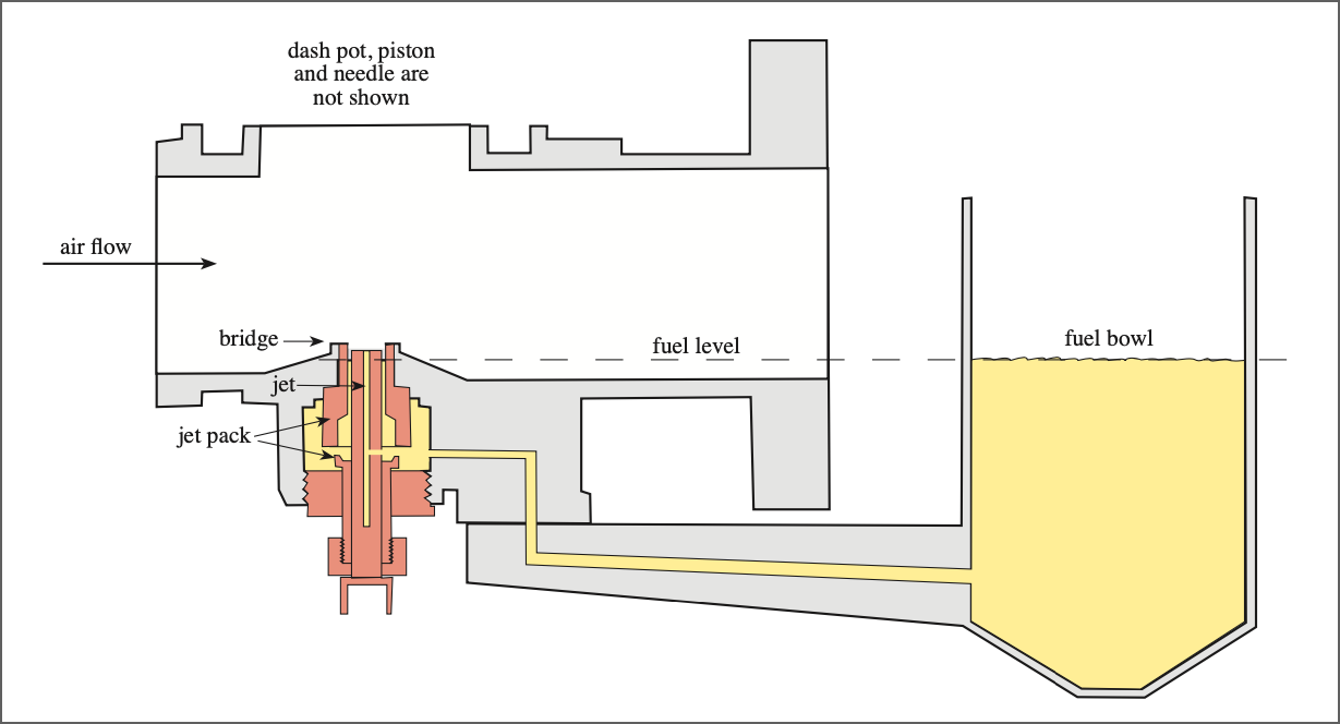
 These elements can be seen in the simplified cut-away diagram of an SU carburettor. Channels in the body allow air to move between the different parts of the carburettor and fuel in the float chamber can go through into the bottom of the jet. So the air/fuel ratio is automatically adjusted for all conditions.
I've had a problem with the carburettors on TC4985 since I bought it in 2015. Actually there are three problems, although only two have been present from the start of my ownership. The engine runs well and others have commented on how well it pulls. However, I keep a record of the amount of fuel that I put in the tank and of the milage at the time, so I can roughly calculate a rolling average fuel consumption. I would expect it to be about 35mpg, but found that it has been consistently less than 25mpg. I also found that the plugs are sooty, particularly those in cylinders three and four. Clearly it is running too rich!
If you're wondering about the third problem then that is about bolts on the carburettors that work loose and allow fuel to seep out. I've tried thread lock, but that only lasts for a few hundred miles (but see later).
I've had cars with SU carburettors before, even one with twin carbs, so I had some idea about tuning them. Nevertheless I read any articles that I could find and confirmed that you need to synchronise (balance) the pair, set the fuel height in the float chamber (and thus in the jet) and then adjust the mixture to get the right idle behaviour. The tapered needle, attached to the moving piston, then deals with the varying demands.
Balancing twin carburettors is all about getting the same volume of air going into each carb. In the past I've done this by listening (through a length of flexible tubing) to the hiss made by each carb as the throttle is opened, then adjusting the link between the two butterfly throttle valves so as to alter their opening. However, for TC4985 I borrowed a mercury manometer from a neighbour, connected its tubes to the two bleed points on the inlet manifold and found that the two carburettors were perfectly balanced.
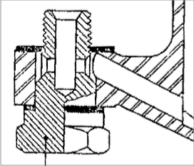
 On pages 27-40 of the May/June edition of the 'Sacred Octagon', published in some undeclared year, F.E. Old, the Technical Editor, published an article called 'BACK TO BASICS #11: CARBURETOR TUNING'. He included this diagram to help describe how to set the fuel level in the float chamber and thus in the jet. The diagram shows the top of the float chamber, turned upside down. I used a 7/16" diameter bolt to set the float lever.
With the carbs balanced and the fuel level set in the two float chambers, I wound the jet adjusting nuts up and down (keeping the two at the same setting) to adjust the amount of fuel entering the carbs at idle. You can adjust the idle speed using a screw on each butterfly spindle. Every description of how to tune SU carburettors has a graph of engine speed against time similar to this one.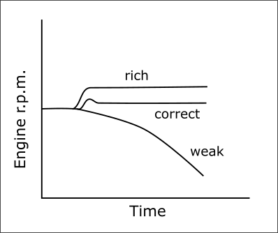
If you raise the piston by 1/32" and the tuning is correct, then the engine speed should rise slightly. In the past, on various cars, I've never really been successful in finding that point. Perhaps there is just too much wear in various parts of the carburettors and engine for them to behave as described.
An Alternative Approach
I subscribe to an online forum for TA, TB and TC models. In June 2022 someone posted an extract from an article by Manley Ford called 'Taking the Mystery Out of SU Jet Heights' on that forum. The extract was:
Fuel should be visible in the jet tube (remove the carb dashpot and piston and turn on pumps to see where it settles). We actually set the jet tube height relative to the top of the bridge and NEVER subsequently touch the jet height (i.e. don't mess with raising/lowering the jet with the screw at the bottom of the carb). We've found that the top of the jet should be between 0.060" and 0.065" below the top of the jet bridge. Best atomization happens with this "jet drop." With the jet higher than that, the fuel actually "mists" too much, and with the jet lower than that, it actually "puddles" and doesn't atomize well enough. Once the jets are set relative to the bridge height, the next step is to set the fuel level in the float bowls. You should see the fuel about 1/8" to 3/16" below the top of the jet tube. Any higher and it's likely spilling over when the motor fires/vibrates. Blow down in the jet tube (with pumps running) to see where the fuel level settles.

The person who quoted Manley Ford also kindly included these two diagrams to illustrate the method. Manley Ford doesn't say how they measured the degree of atomisation, but, being a scientist and engineer, I like the idea of using experimentation to determine the best conditions, so I thought that I would give it a try.
In the past I'd found adjusting the fuel level in the jet, by bending the float lever, to be a laborious process. For each adjustment you need to remove the float chamber lid (being careful not to loose the lever pin or the needle), remove the lever, bend it and then reassemble it all. Adjusting the level of the jet with respect to the bridge is easy, using a vernier calliper to measure the gap, but getting the fuel level to be within the specified range was much more difficult. You can pull down the choke lever so as to lower the jet until the meniscus of the fuel is at its top, but I found that the level oscillated above and below the range with each adjustment. Eventually I had both within range.
The Third Problem
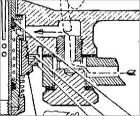 Before I had a chance to take the car for a test run I hit problem number three. As usual, fuel was leaking from the 'hold-up' bolt on the front carburettor. This is the bolt that holds the float chamber to the body of the carburettor. As you can see from these two diagrams (also taken from Old's 'Back to Basics #11') that these bolts are quite complex, allowing fuel to flow through them and having two sealing washers, one either side of the float chamber. So I put a socket on it and, gritting my teeth (the carburettor body is made of MAZAK, an alloy of zinc, aluminium, magnesium and copper, and is quite soft) I tightened the bolt. Then suddenly it went loose; the thread had stripped!
 When I disassembled the rear carburettor I found that the thread had partly broken up, so I needed to repair both carburettor bodies. As you can see from the diagram, it is a blind hole with a drilling for the fuel channel, so I decided that replacing the thread was best left to an expert. The repair, by the way, is done by drilling out the hole, tapping it to put in a new thread and then inserting a Helicoil (I think other brands are available) with the original thread. So I contacted Burlen, who sell SU carburettor parts and recondition whole units. I was able to speak to the person who would do the work, which was reassuring, and so sent off the two bodies, stripped of all the other components.
After a couple of weeks they were returned. The underside of one of the carburettor bodies is shown in the photo, where the new thread and machined surface are visible. The Helicoil, being made of steel, provides a much stronger thread for the hold-up bolt.
After reassembling and refitting the carburettors and then re-balancing them, it was time to tune them. Having missed the South Downs Run due to the stripped thread and wanting to be ready for the next Sussex Wanderers outing I thought that I would, at least in the first instance, use the conventional method of tuning. So I set the fuel level using a 7/16" bolt and wound down each jet adjusting nut by six flats. Then I wound them up, each by the same amount, until the engine revs didn't drop when lifting the pistons. After going for a fairly long test run (about 20 miles). The engine was stuttering a little on deceleration and the plugs were still on the sooty side. So up another flat and another test run. This time I stopped en route and made another adjustment, with noticeable improvement. The car then ran well on the 69 miles Wanderers outing. So it was time to quit while ahead.
Therefore the leakage of fuel is fixed (although there is still just a little weeping from one jet) and the hold-up bolts are now firmly tightened, but it will take a while before I know if the fuel consumption has improved. As for the alternative method of carburettor tuning; that will have to wait for another day.
(Written 31st October 2022; published in October 2023.)
© David James 2022 Last updated: 12th October 2023