Balance Resistors
If you are an owner of a post 1976 MGB or V8 you are probably familiar with the concept of ignition coil ballast resistors, since your car contains one. However, it wasn't a term that I'd come across. It first appeared on my radar when a friend (and TC owner) noticed that my TC had been converted from positive earth to negative earth and asked if I (the TC) had a 'negative spark' at the plugs (more on that later). Due to an incorrect measurement that I made, he suggested that I might need a ballast resistor. However, before we talk about these devices it is worthwhile to explore some of the basics.
Ignition Coil Operation
For the air/fuel mixture in an engine cylinder to ignite you need a spark across the electrodes of the spark plug. In order to generate that spark you need a high voltage across that gap; a voltage significantly higher than that available from the 12V battery. In fact, something between 12,000 and 25,000 volts!
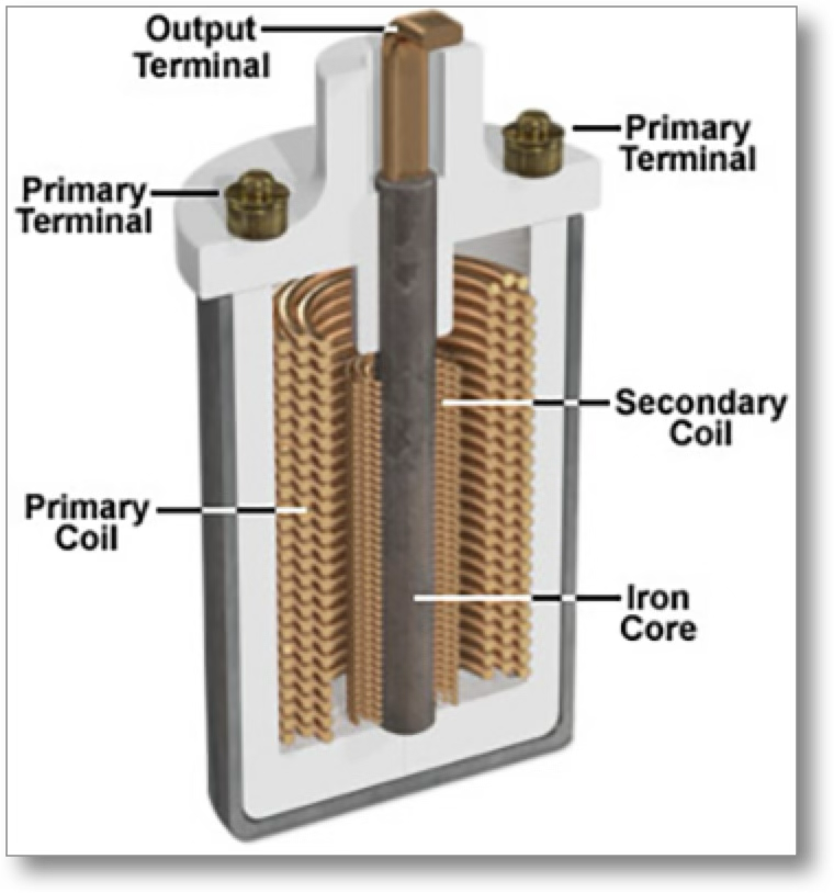
 To achieve this massive uplift in voltage, the ignition coil uses the phenomenon of magnetic induction, where an electric current induces a magnetic field (a principle used in all electric motors and generators). As you can see in the diagram, the ignition coil in fact has two coils, a primary and a secondary, wound around an iron core. Once the ignition key is turned, 12 volts from the battery is applied to one end of the primary coil, the other end being connected to earth via the contact breaker points in the distributor. The current flowing in the primary coil, when the points close, creates a magnetic field, which induces a current in the secondary coil. The end of the secondary coil is connected to the distributor via a high tension lead. The primary winding is made of thick copper wire with approximately 200 windings, whereas the secondary winding is made of thin copper wire with approximately 20,000 windings. Thus the increase in voltage.
Negative spark
Before moving on to the main topic of this article let me just explain what is meant by a 'negative spark' and why it is beneficial. By convention we talk of an electric current flowing from positive to negative, for example from the positive terminal of a battery to the negative terminal. However, an electric current is actually a flow of electrons which, being negatively charged, move from negative to positive. So our spark at the plug is due to the air breaking down and allowing the electrons to flow across the gap. Now it seems that the hotter central electrode of the spark plug will emit electrons more freely than the cooler spark plug body, thus having the central terminal at a negative voltage with respect the the car's earth (the spark plug body) will produce a better spark. As an aside, although my TC has been changed to a negative earth and has a modern ignition coil, it has been wired so as to produce a negative spark.
Ballast Resistor
To reward you for getting this far I'll finally talk about ignition coil ballast resistors!
You are probably aware that when the starter motor is cranking the engine, the voltage that is applied to the rest of the system is reduced. On my TC, for instance, the voltage drops from nearly 12 volts to about nine volts. Since the voltage reaching the ignition coil is reduced at this time, the voltage applied to the spark plugs is also reduced and the spark is weaker; just at the point when you want it to be good. This is where a ballast resistor can help.
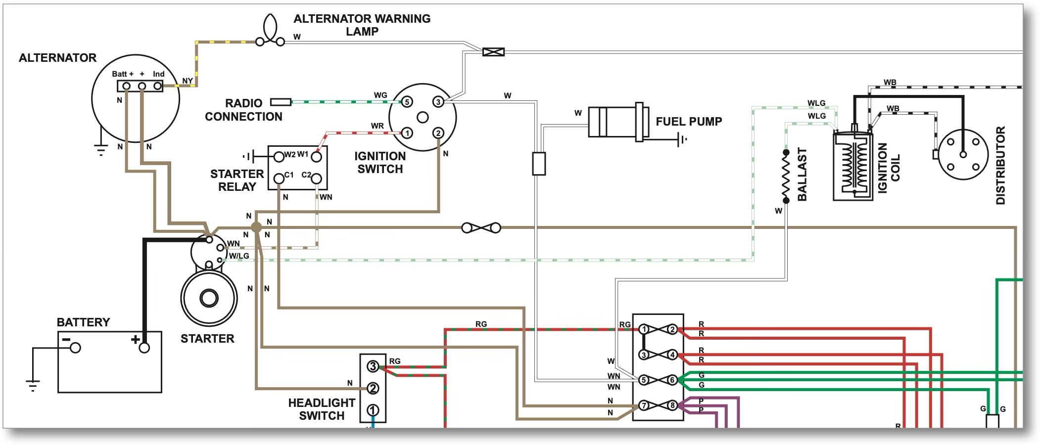
The aim is to provide a stronger spark during cranking the engine; stronger than that provided during normal running. This is provided by a combination of three components, a ballast ignition coil, a ballast resistor and a wire from the starter solenoid to the coil. These can be seen in the portion of a 1975/76 MGB wiring diagram taken from a Haynes manual.

- A ballast ignition coil is one that has a primary coil (the one to which the battery voltage is applied) with a lower electrical resistance. You will recall from Ohm's law that if you halve the resistance then you will get the same current for half the voltage. So if you halve the resistance of the primary coil, you will only need six volts to get the same strength of spark.
- But, of course, we have a 12 volt supply from the battery. So a ballast resistor placed between the ignition switch and the coil will lower the voltage applied to the coil.
- By connecting the coil directly to the starter motor solenoid you get a higher voltage applied to the coil, but only while turning the engine with the starter motor.

Although the voltage will still drop below 12 volts while cranking the engine, it will still be higher than the voltage applied during normal running and so improve the chance of the engine firing. If that higher voltage was left permanently applied to the coil then the coil would overheat and soon fail.
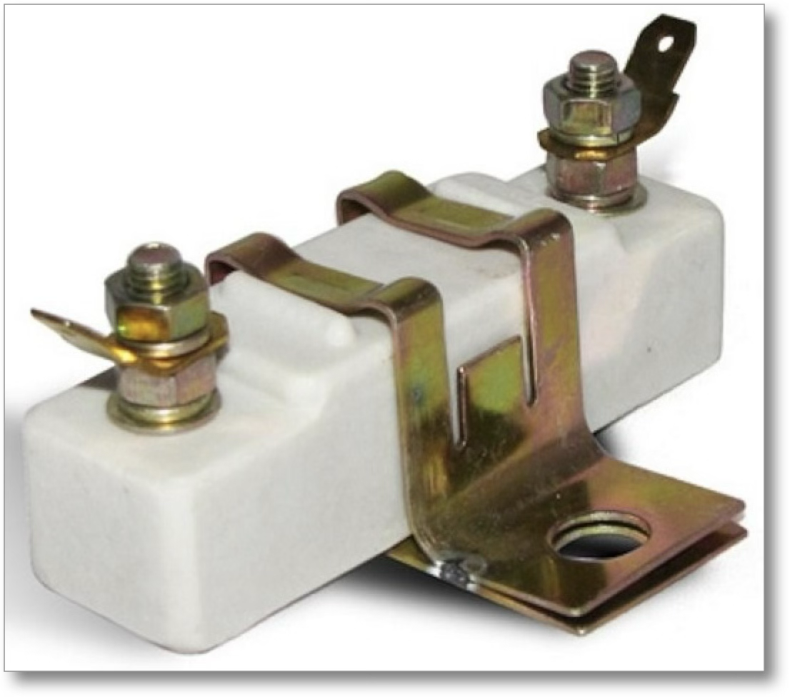
I started by saying that post 1976 MGBs and V8s had a ballast resistor. Actually they have a ballast wire. You can see here a typical stand-alone ballast resistor that would be bolted somewhere near the coil and wired in series with the coil, but the ballast resistor that you can see on the wiring diagram extract is a high resistance wire that is built into the wiring loom. The thing to remember, however, is that, if you need to replace the ignition coil, you must use a ballast coil (rather than a non-ballast coil) so that it will give a good spark at its reduced voltage.
(Written 31st March 2025; published in WSMGOC Main Gear, Month Year.)
© David James 2025 Last updated: 31st March 2025